
The side object system is a framework that can be used to generate different type of objects along the spline shape. Think of fences, walls, guard rails, lampposts but also more complex shapes like rivers, terrain detail surface overlays. You can create your own side objects using your own assets.
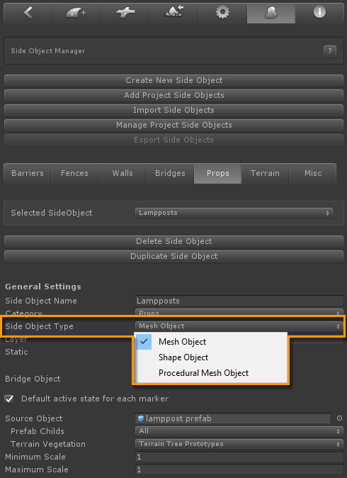
Side Object presets are created in the Side Object Manager, the 2nd tab from the right.
There are three types of side objects:
Per side object type you have a range of controls at your disposal. We recommend to take some time and experiment with the different settings and see what effect they have in the scene.
Below we will look at several side objects in the demo project, explaining why a specific side object type was chosen and specific settings.
You are free to use these side objects in your own projects. Click here for a tutorial how you can export a selection of side objects from a project and import them in another project.
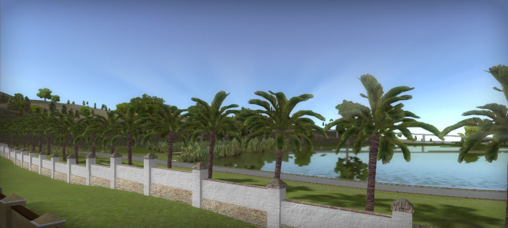
This wall mesh consists of two pieces, the pillars which are wider and the middle segments. This setup supports smaller height differences with the horizontal alignment. Because of the horizontal alignment we cannot use the Procedural Mesh object type which will generate the wall in all 3 directions alogn th spline shape. So we use the standard Mesh Object for this.
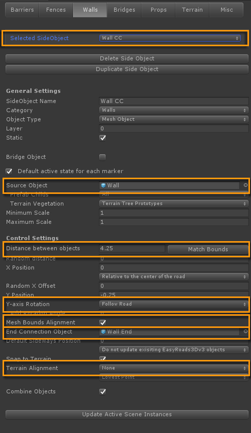
Source Object: The "Wall CC" prefab is assigned as the source prefab.
Distance Between Objects:For the Mesh Object type, instances will be positioned at X Distance between each other. We want this distance to match more or less the size of the wall. The "Match Bounds" button (on the right of the "Distance between objects" field) can be used for this. This will set the distance according the bounds of the source object. We reduced the value to 4.25 so the middle segment stick slightly into the pillar. This will deal with sharper bends.
Y-axis Rotation: As the forward of the wall instances should point in the x, z direction of the spline curve, "Follow Path" is used for the Y-axis Rotation (the forward direction).
Mesh Bounds Alignment: Since the instantiated wall pieces should connect "Mesh Bounds Alignment" is checked. This will align the start and end of the instances exactly on the spline curve based on the bounds of the object. The next instance will nicely connct with the previous
End Connection Object: The source object only has a pillar at the start otherwise the wall will be generated with two pillars next to each other. But this will result in a missing pilar at the end. Therefore, the "Wall End" prefab, the pillar only, is assigned as the End Connection Object. This object will be instantiated at the end of the wall.
Terrain Alignment: We want this typical stepped look horizonal alignment on the wall in non flat areas. To achieve this, "Terrain Alignment" is set to None.
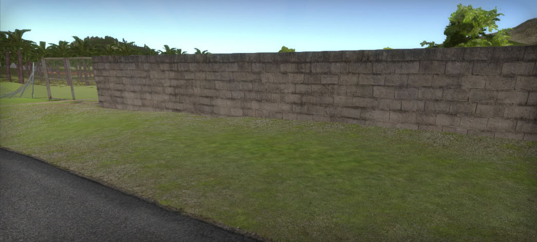
Because this wall type has a uniform shape without pillars between segments, each segment should perfectly connect to the previous. The Procedural Mesh Object does exactly that. The wall follows the spline shape in all directions, no stepped instances like in the previous example.
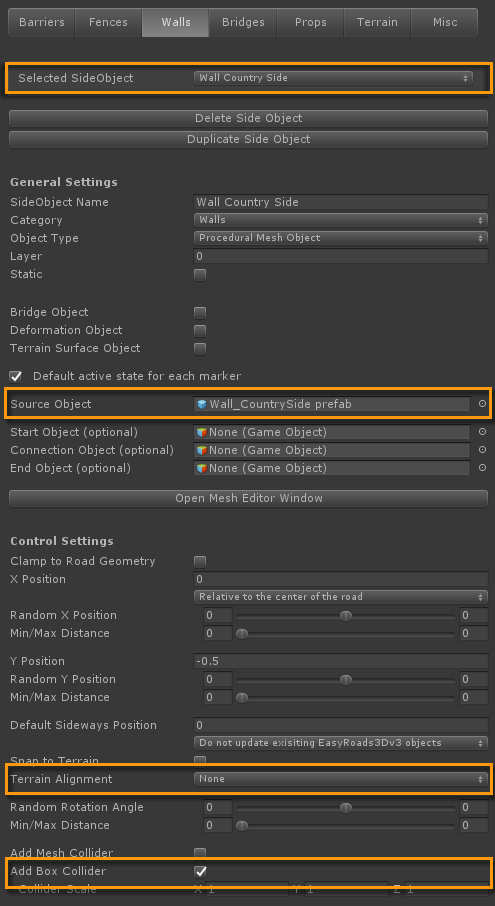
Source Object: The "Wall_CountrySide prefab" is assigned as the source prefab.
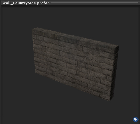
The source mesh is modelled in a modelling app and includes start / end caps which will be placed at the start and end of the wall.
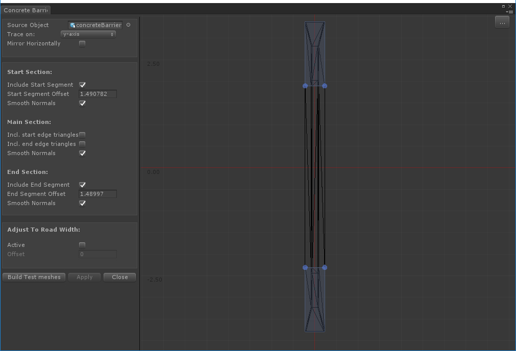
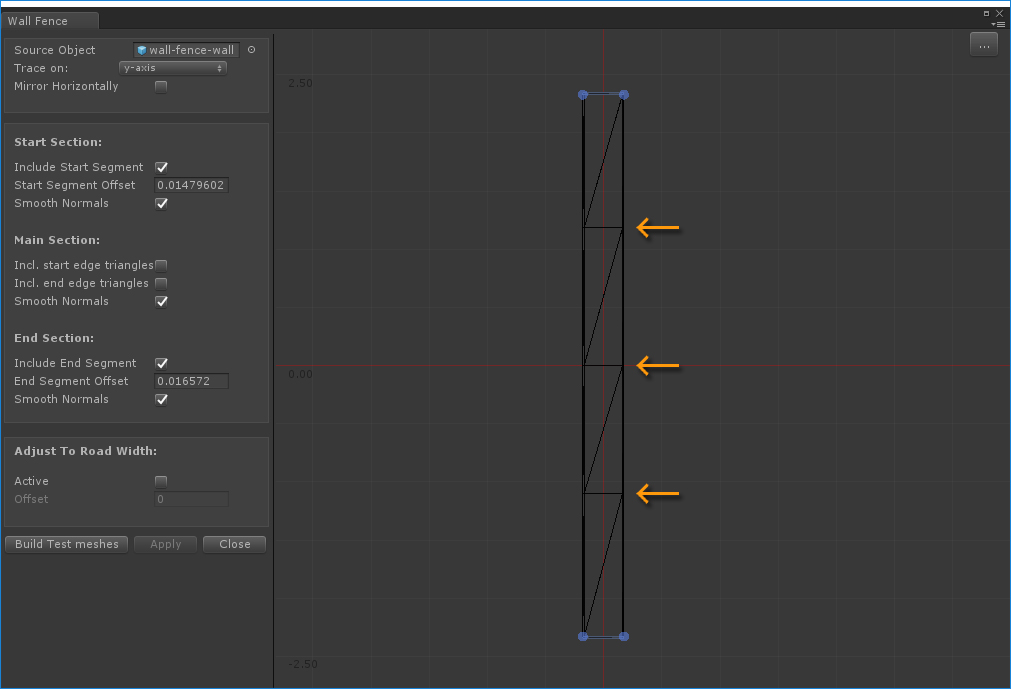
To achieve this, the side object needs to be configured so the system knows which parts should be usedd as start/ middle/ end segments. This is done in the Mesh Editor Window, the "Open Mesh Editor Window" button.
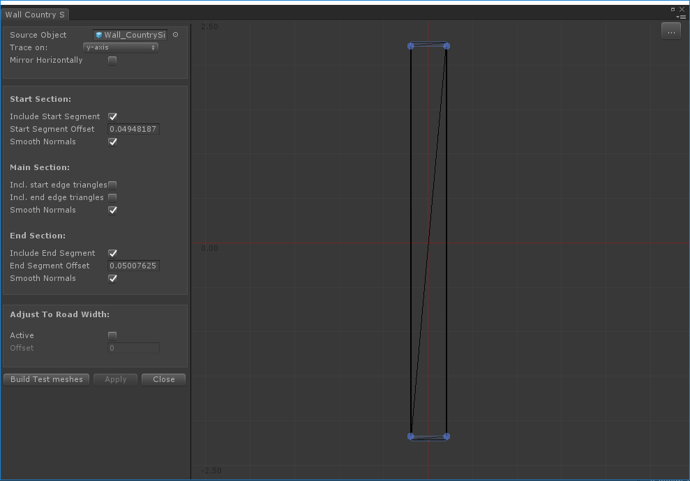
The wall is visible on the canvas in top down view. Hit the Z key if you cannot clearly see it. The Z key will put focus on the object.
Both the "Include Start Segment" and "Include End Segment" checkboxes are active. You will see blue handles on the canvas. These represent the start (bottom handles) and end (top handles) offset. Zoom in (scroll wheel or press right button and move up/down) so you can clearly see the geometry. The blue handles are located at the edges between the main wall segment and the start / end caps. When moving the handles upwards/downwards, they will snap to vertices once they are within a specific small range.
"Smooth Normals" are active because we want smooth normals between the generated segments, not sharp edges.
Close the Mesh Editor window.
Terrain Alignment: Although the wall should follow the spline shape (which is automatically the case for Procedural Mesh side objects), it should be generated without any additional rotation. Therefore "Terrain Alignment" is set to None. You could use one of the path alignment options but in that case the wall will be oriented relative to the path. This is not a problem on a flat terrain but it will not look realistic when the start or end of the wall is in an area where the road points upwards or downwards.
Add Box Collider: Because the wall has a fairly simple box type of shape for each segment, Box Colliders are used here.
The setup of this side object is almost identical to the Country Wall explained above. The start / end segments in the Mesh Editor Window are more clear.
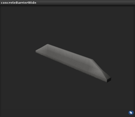
This model is set up to be used on motorways, roads with no sharp bends. The relatively long middle section makes it less suitable for strong bends.
The difference in the side object setup with the above wall is the alignment.
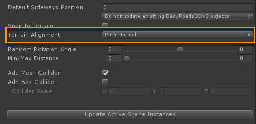
Terrain Alignment is set to Path Normal. The barrier will align exactly with the road.
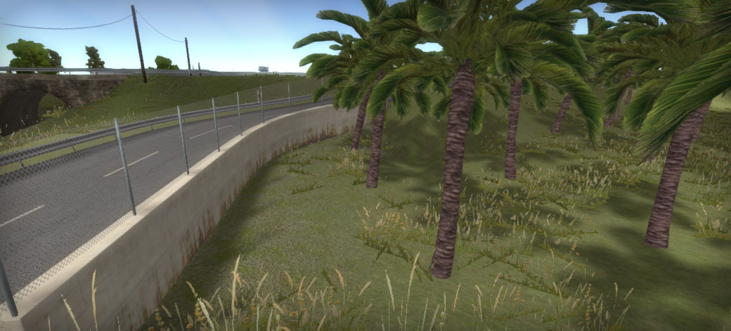
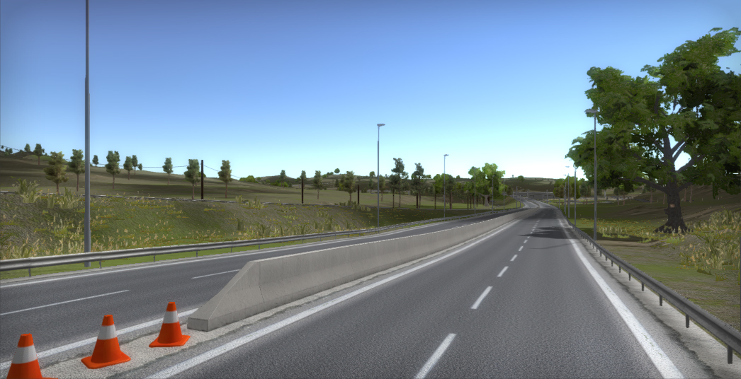
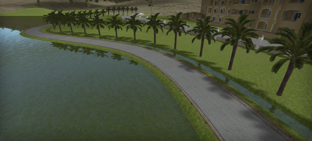
The concrete barrier example above is optimized for motorways which do not have sharp bends. The setup of this "Wall Fence" side object is almost identical. This time however we want to connect the wall with the road and it should support reasonably strong bends. For Procedural meshes each vertex will be calculated relative to the spline shape. Therefore making the source mesh more detailed in the middle segment will result in a smoother wall in stronger bends.
We could have made the wall smaller instead but that will result in a more visible repetitive texture pattern.
In the above screenshot the terrain on the right is clearly leveled lower then the road. To achieve this effect, the respective markers 4 and 5 are selected (by holding the Shift key) and in the marker section in the Inspector "Align with the terrain" is selected from the dropdown for "Right Indent Alignment". This will snap the indent points to the ground instead of aligning them with the road height.
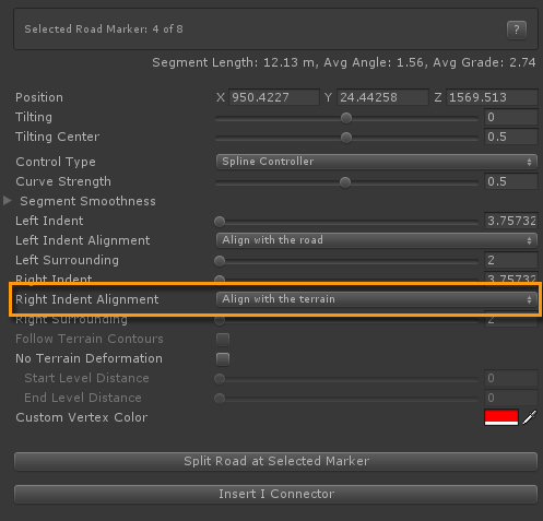
For side objects marked as Terrain Surface Object (Side Object Manager > General Settings > Terrain Surface Object), snapping the indent points to the ground instead of aligning them with the road height will happen autmatically. However, this side object isn't always used that way.That is why we manually set the "Right Indent Alignment" to "Align with the terrain".
Here we created a palm tree line following the spline shape. This palm tree is part of the terrain object as a vegetation prototype. In Edit Mode the palm trees are instantiated in the scene. In Build Mode they are added as tree prototype instances to the unity terrain object.
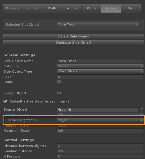
Terrain Vegetation: All the available terrain vegetation prototype are listed here. "pb_Hi" is selected an automaticaly assigned as the Source Prefab.
Random Distance: A small value of 0.5 is used to add some variation in the distance between the instantiated trees.
Random X Offset: A small number of 0.25 is used for some variation in the X direction (sideways).
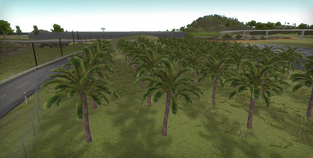
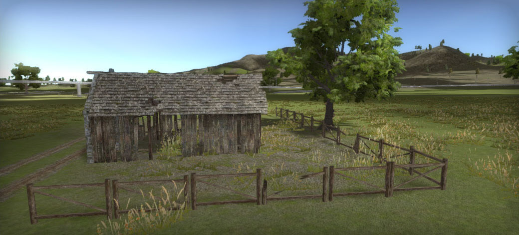
This is more about using side objects in the scene and create a pattern of objects like in the above image.
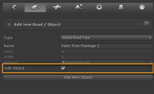
Create the first object. We created a new object as "Side Object", no road will be created, added two markers and activated the Palm Trees side object in the Terrain tab.
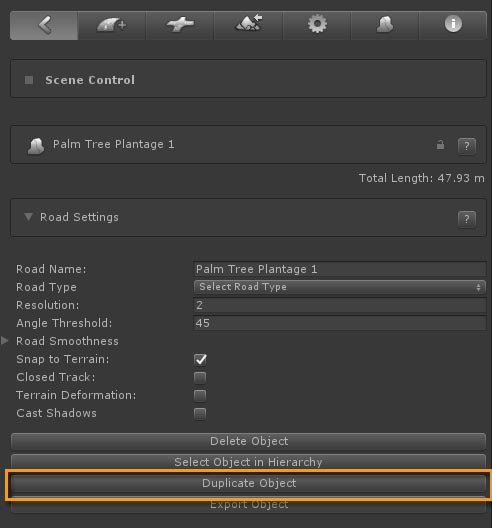
Afterwards we pressed the "Duplicate Object" button. The object will be copied and all markers are instantly selected so you can easily move the object (sideways in this case). These steps were repeated for each line of palm trees.
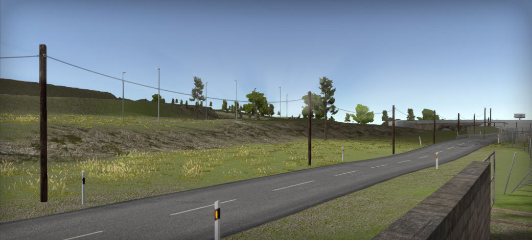
Here we have an example of how you can create powerlines. Since the powerline segments should perfectly connect, a Procedural Mesh Object is used.
Both the pole as the wire (a simple quad in this case) were modeled in a modelling app. The pole at (0, 0, 0) and the quad in the forward direction starting exactly at the connection point with the pole. Please review the original "electricity pole wood.obj" in your modelling app.
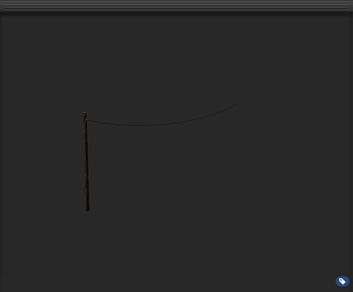
In Unity we created a prefab with only the wire, "powerline wood single prefab", and a prefab with only the pole, "powerline wood single pole prefab"
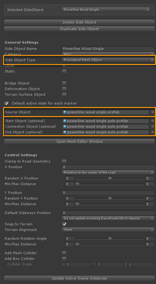
Source Object: "Powerline wood single prefab", the wire. Since this doesn't involve start / end caps and Smooth Normals doesn't really have an affect here, there is no need to change anything in the Mesh Editor Window.
Start Object: "Powerline wood single pole prefab", the first pole instance at the start.
Connection Object: "Powerline wood single pole prefab", a pole instance for each new segment.
End Object: "Powerline wood single pole prefab", the last pole instance at the end.
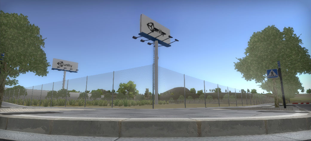
The setup of this side object is very similar to the powerline discussed above.
But for the fence random rotations are used to make it look more realistic.
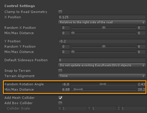
Random Rotation Angle: Values have been added for both directions, these represent the max random angle.
Min/Max Distance: This represents the distance over which each random rotation section will take place.
The Guard rail side objects are another example where random rotations are used to make the rail look less computer generated.
Optionally these random rotation settings can be adjusted per road object and manually per marker.
The Source Mesh
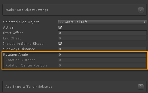
The setup of this side object is similar to the Concrete Barrier discussed above with Start / End gaps.
Two things to add here:
In order to have the poles added correctly, the setup is done in a way that the bottom pole is added to the Start Segment and the top pole to the middle segment. This results in the bottom pole being added at the start, the top pole is repeated for every middle segment and also included on the end segment.
Alternatively the pole geometry can be split in the middle and aligned exactly with the edges of the guard rail. That way the poles per segment are split in halves and "glued" together when creating the geometry, also for start / end segments. It will result in more geometry for this guard rail as the pole must be split in two halves. In this case we use a fairly simple pole to keep triangle count low so we chose for this setup.
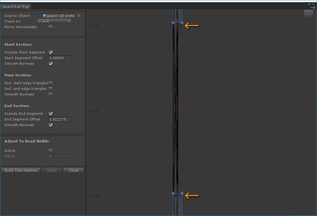
The other approach was used on the guard railings on the race track. For the small race track barrier we simply rotated the horizontal element 45 degrees so the triangle edges are located exactly on the start / End offset edge. So in this case it does not result in more geometry.
Duplicating Side Objects
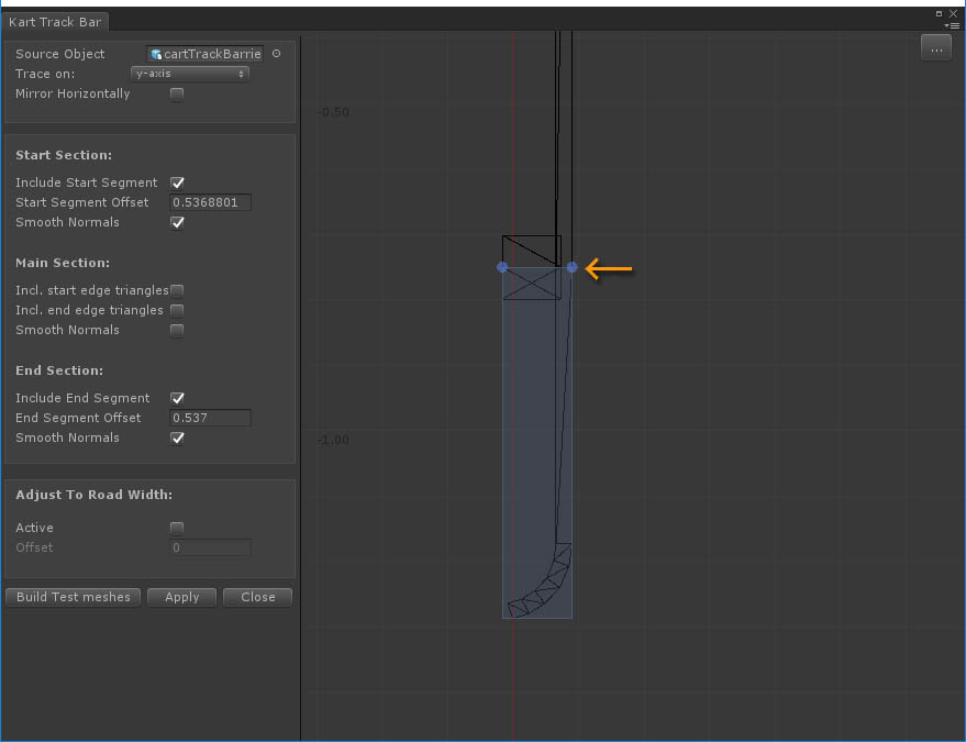
The left Guard Rail version was created by duplicating the right version ("Duplicate Side Object" below the "Selected Side Object" drop down).
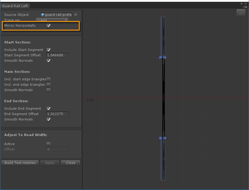
The right version was duplicated, renamed to "Guard Rail Left" and in the Mesh Editor Window "Mirror Horizontally" is checked. This will flip the geometry.
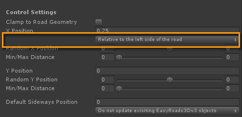
In the Side Object Manager Control Settings, "Relative to the left side of the road" is selected for the X Position alignment whereas "Relative to the right side of the road" is selected for the"Guard Rail Right" side object.
Smooth Normals
In the above thumbnail Smooth Normals for the main section is switched off. This is temporarily. The smooth normals calculation process for this mesh type is fairly long. So for now, duing development we switch it off. General Settings > Scene Settings has an additional optimization option for this: "Calculate Smooth Normals Side Objects in Edit Mode". This will still calculate Smooth Normals when switching to Build Mode. By toggling off Smooth Normals in the above window, they will never be calculated up until we toggle this back on.
We will also look further into optimizing the calculation process itself.
Just like the Wall CC side object discussed further above, this side object uses the "Mesh Object" type.
Fence objects are instantiated at a distance equal to the bounds of the prefab ("Match Bounds" button) + a small margin in this case and a very small random margin.
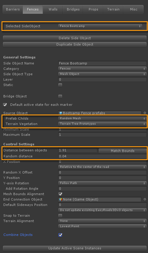
But contrary to the Wall CC side object which is based on a single source prefab, this fence uses a source prefab with a range of variations as child objects. The final fence in the scene will be build by selecting these child objects randomly.
Source Object: "Bootcamp Fence prefabs"
Prefab Childs: "Random Mesh" is selected. For each instance one of the childs will be selected randomly. This is how the prefab was setup. All fence segment variations are added as childs to the source prefab. For each instance a single child object will be randomly selected.
Because we like to have some variations selected more often then others, we simply duplicated these objects several times so there is more chance they will get selected.
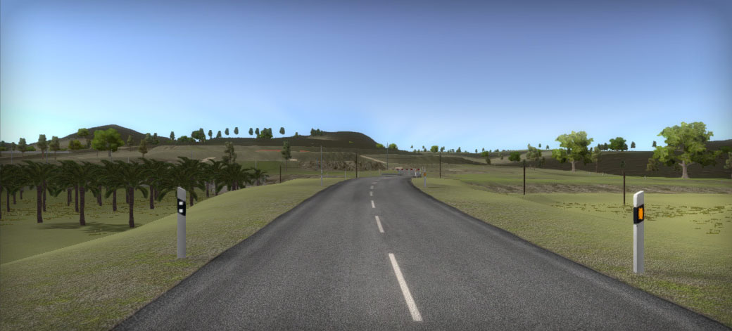
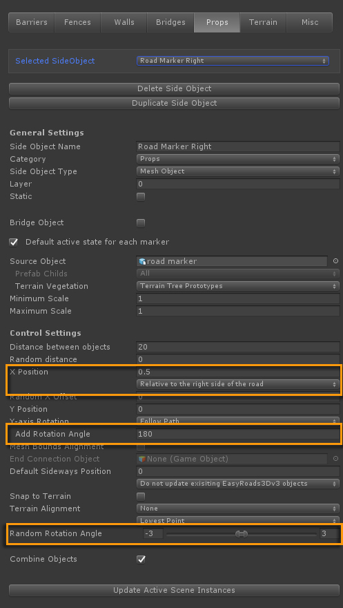
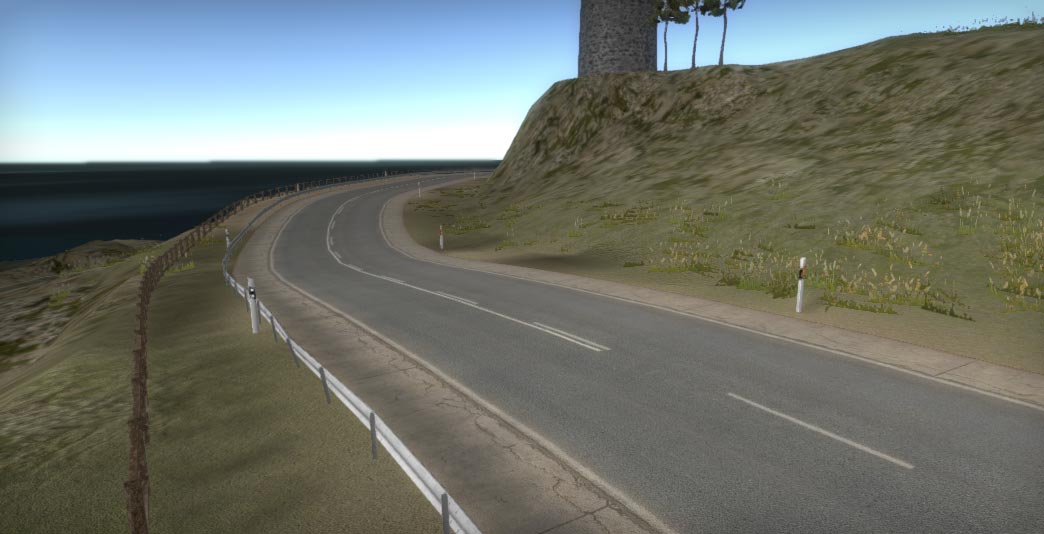
The "Road Marker Right" and "Road Marker Left" side objects are identical apart from three settings. The X Position value for the left version is negative and the alignment is set to "Relative of the left side of the road".
Unique for the right side version is "Add Rotation Angle". The marker prefab has two sides with different reflection textures, see the above screenshot. The right side version should be flipped. This is done by entering 180 for "Add Rotation Angle".
These two side object also have a random rotation angle assigned between -3 to 3 degrees. This a rotation sideways on the x-axis, it will make the poles look more realistic, less computer generated. These rotation settings are editable per road so you can for example make the rotations stronger on older roads.
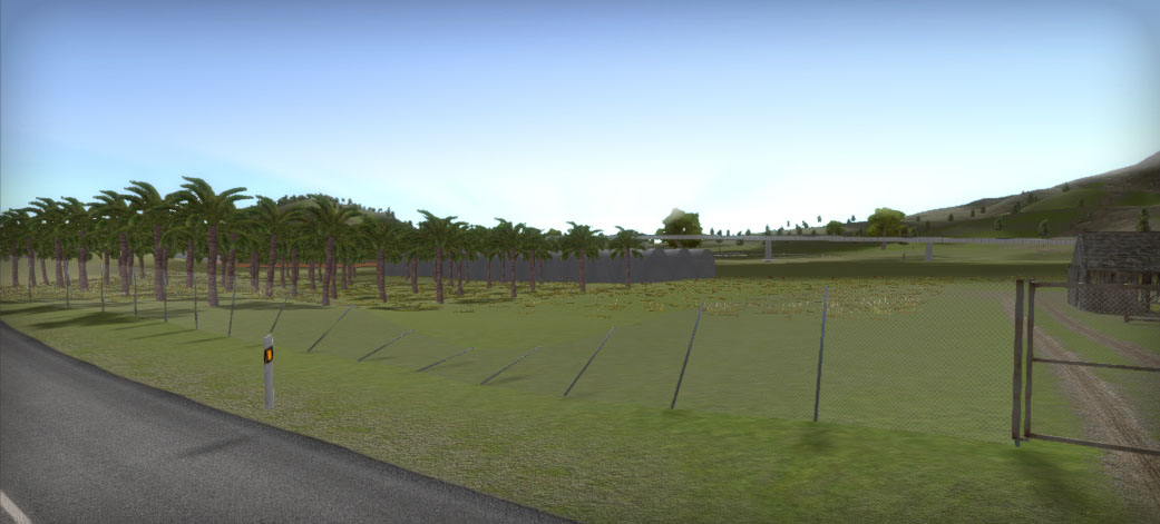
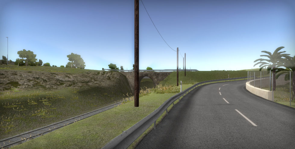
This fence has a manual rotation applied near marker 3.
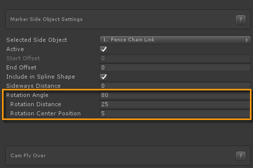
Select marker 3 and scroll downwards in the Inspector to the Marker Side Object Settings. "Fence Chain Link" is auto selected in the dropdown as it is the only side object active on this object.
The "Rotation Angle" is set to 80, the rotation distance from start to end is set to 25 and the center position is set to 5 units after the marker.
This is an alternative for separate road textures with additional line markings. The side object is a Shape type of side object aligned with the road and slightly raised.
Currently the layer is set to layer 0, but for optimization purposes you could set it to a different layer and use a culling distance for that layer.
